
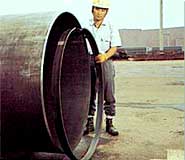
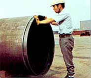
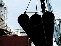
The photographs show how bevel protector is installed.
The protector is made of a steel strip forming into a
circular shape.
The abutting ends of the ring are fitted with steel wedge
clasps.
Bevel protectors of the type shown in the photographs are
used for large diameter line pipe.
The wedge, which has either machined reverse teeth or
plain edges, is inserted into the claps and tapped into
place to expand the protector inside the pipe end.
This protects the vulnerable root face and bevel against
damage during subsequent handling from mill shipment to
arrival at the job site.
 |
 |
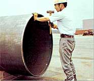 |
| Installation of bevel protector (in sequence from left to right) |
• Example of Bevel Protector

Improper practices or careless handling are likely to result
in pipe damage of the following types:
| (a) |
Denting, ovalling |
— |
caused by use of improper supports or stacking to excessive
heights. |
| (b) |
End damage |
— |
caused by use of improper end hooks for lifting or by
rough handling in which the pipe end is struck. |
| (c) |
Fatigue cracking |
— |
caused by vertical vibrations during transportation as
a result of excessive static and cyclic loads. |
| (d) |
Abrasion, scratching |
— |
caused by the pipe wall being rubbed or struck against
other objects. |
Handling
Hooks
Hooks shall be designed to prevent end damage and shall
be lined with rubber. They shall also have sufficient width
and depth to fit the inside of the pipe.
Lifting
Lifting shall be carried out so as to prevent impact loads
that could cause local denting or out-of-roundness of the
pipe body or pipe ends.
Bevel protecting
Bevel protectors which are loose or missing shall be
reattached to the pipe end before the pipe is handled.
Storage
The surface on which the pipe will be laid or stacked shall
be flat and free of protrusions. Bearing strips shall be
carefully leveled to provide uniform load distribution.
Loading Tiers and Bottom Dunnage
The maximum allowable number of loading tiers the
stowage of steel pipe cargoes (with D/t over 50) is
calculated by the following formulas:
| n |
= |
Loading tires |
| P |
= |
Stowage method/length of vessel |
| P |
Stowage
Method |
Length
Vessel |
120m
-
160m |
160m
-
180m |
180m
-
200m |
Over
-
200m |
Remarks |
| a. |
 |
5.65 |
6.05 |
6.25 |
6.78 |
Theoretical figure.
not suitable for
calculation. |
| b. |
 |
3.07 |
3.29 |
3.54 |
3.69 |
In case of 1 point
support. |
| c |
 |
17.19 |
18.40 |
19.82 |
20.62 |
Theoretical figure.
not suitable for
calculation. |
| d. |
 |
6.85 |
7.33 |
7.90 |
8.21 |
In case of 2 point
support. |
| D |
= |
Outside diameter (mm) |
| t |
= |
Thickness of pipe (mm) |
| σγ |
= |
Minimum yield point (kg/mm²) |
(2) Variations in (n) occurring with the use of bottom
dunnage.
| L |
= |
Pipe length (m) |
| B |
= |
Number of pieces of bottom dunnage |
| W |
= |
Width of bottom dunnage (m) |
 |
|
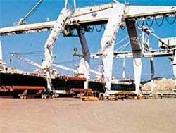 |
| Pipe loading |
|
Yard-to-ship loading facility |
|